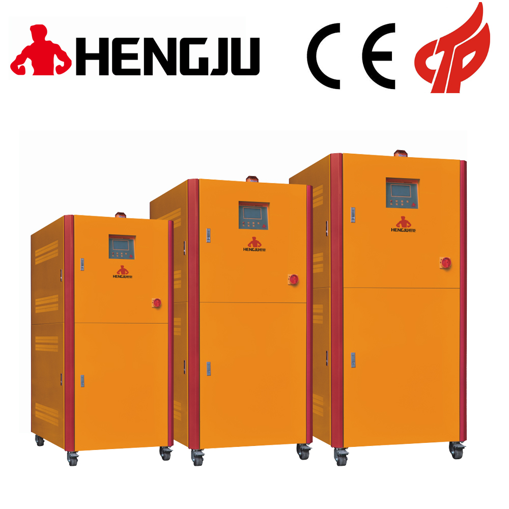
Manufacturing method of plastic dehumidifying dryer
[Patent Abstract] This utility model discloses a plastic desiccant dryer, which includes a drying barrel, and also includes an air compressor, a dehumidifier, a heating blower, a heater, an exhaust exhauster, and a dehumidification filter, wherein the The air compressor is connected to the inlet of the heater through a pipe, the outlet of the heater is connected to the inlet of the drying barrel through a pipe, and the inlet of the exhaust air compressor is connected to the outlet of the drying barrel through a pipe, The outlet of the exhaust gas exhauster is connected to the inlet of the heating blower, the outlet of the heating blower is connected to the inlet of the heater, and the dehumidification filter is arranged at the top of the drying barrel. The new structure is simple and low in cost.
【Patent Description】
Plastic desiccant dryer
Technical field

[0001] This utility model relates to the technical field of plastic production, in particular to a plastic desiccant dryer.
【Background technique】
[0002] Poor molding of plastic products, including poor impurities, pouring channels, burrs, bubbles, flow marks, cracks, poor dimensional stability, internal stress, insufficient product physical strength and other shortcomings, a large number of which are caused before molding Plastic impregnation is caused by sufficient dehumidification and drying. Especially high water-soaking plastics such as PET, PBT, PA, PC, etc. need to be fully dehumidified and dried. Therefore, the American Plastics Association recommends that the plastic before molding must be dried to a rate of less than 0.02% to solve the problem of poor molding of plastic products.
[0003] Chinese patent number ZL200820092846.2 discloses a dehumidification drying feeder, including a drying system and a feeding system, the drying system has a non-heat regeneration device, the non-heat regeneration device includes a reversing Valve, the first dehumidification bucket, the second dehumidification bucket, the first one-way valve, the second one-way valve, and the throttle valve, the lower ends of the first dehumidification bucket and the second dehumidification bucket respectively pass through the reversing valve and the external compressed air pipeline Connected to the silencer filter, the upper ends of the first dehumidification barrel and the second dehumidification barrel respectively pass through the first one-way valve, the second one-way valve is connected to the drying fan inside the drying system, and the upper end of the first dehumidification barrel is connected to the second The dehumidification and drying process directly passes through compressed air to obtain dry air with low dew point after dehumidification. However, the structure of the equipment is complicated and the manufacturing cost is high, and it is not convenient for enterprises to use.
[Utility model content]
[0004] The technical problem to be solved by the present utility model is to provide a plastic desiccant dryer with simple structure and low cost.
[0005] In order to solve the above technical problems, the present utility model provides a plastic dehumidification dryer, including a drying barrel, and also includes an air compressor, a dehumidifier, a heating blower, a heater, an exhaust pressure device, and a dehumidification filter , Wherein the air compressor is connected to the inlet of the heater through a pipe, the outlet of the heater is connected to the inlet of the drying barrel through a pipe, and the inlet of the exhaust air compressor is connected to the dryer through a pipe. The outlet of the hopper, the outlet of the exhaust depressor is connected to the inlet of the heating blower, the outlet of the heating blower is connected to the inlet of the heater, and the dehumidification filter is arranged in the drying hopper The top.
[0006] Further, it also includes a noise-elimination filter, the noise-elimination filter is provided between the air compressor and the heater.
[0007] Further, the drying barrel is an upward blowing hopper type drying barrel.
[0008] Further, the pipe from the heater to the inlet of the drying barrel is a heat-insulating pipe.
[0009] Further, the pipeline between the heating blower and the heater is a heat preservation pipeline.
[0010] Further, the exhaust gas pressure device is provided with an exhaust port, a pressure exhaust port and an outlet.
[0011] The realization of the utility model has the following beneficial effects: the utility model has a simple structure and low cost.
【Explanation of drawings】

[0012] In order to more clearly describe the embodiments of the present utility model or the technical solutions in the prior art, the following will briefly introduce the drawings required to be used in the description of the embodiments or the prior art, in a reduced form, in the following description The drawings may be some embodiments of the present utility model. For those of ordinary skill in the art, other drawings can be obtained based on these drawings without the substitution of costly labor.
[0013] FIG. 1 is a structural diagram of a plastic desiccant dryer provided by an embodiment of the present utility model.
[0014] In Fig. 1, 10-drying barrel, 20-air compressor, 30-dehumidifier, 40-heating blower, 50-heater, 60-exhaust exhauster, 61-exhaust port, 62- Pressure outlet, 63-outlet, 70-dehumidification filter, 80-silence filter.
【detailed description】
[0015] The following will combine the drawings in the embodiments of the utility model to clearly and completely describe the technical solutions in the embodiments of the utility model. It is realized that the described implementation examples replace the embodiments of the utility model, and Not all examples. Based on the embodiments of the present utility model, all other embodiments obtained by those of ordinary skill in the art without labor reforms fall within the protection scope of the present utility model.
[0016] FIG. 1 is a structural diagram of a plastic dehumidification dryer provided by an embodiment of the utility model, as shown in FIG. 1, including a drying barrel, an air compressor, a dehumidifier, a heating blower, a heater, and exhaust A pressure filter, a dehumidification filter, and a sound-eliminating filter, wherein the air compressor is connected to the inlet of the heater through a pipe, and the sound-eliminating filter is arranged between the air compressor and the heater. The outlet of the heater is connected to the inlet of the drying barrel through a pipe, the inlet of the exhaust pressure exhauster is connected to the outlet of the drying barrel through a pipeline, and an exhaust port is provided on the exhaust pressure exhauster, A pressure discharge port and an outlet, the outlet of the exhaust pressure discharger is connected to the inlet of the heating blower, the outlet of the heating blower is connected to the inlet of the heater, and the dehumidification filter is arranged on the drying material The top of the barrel.
[0017] Wherein, the drying barrel is an upward blowing hopper type drying barrel. The pipe from the heater to the inlet of the drying barrel is a heat-insulating pipe. The pipe between the heating blower and the heater is a heat-insulating pipe.
[0018] It should be noted that in this article, the terms "including", "including" or any other variants thereof are intended to cover non-exclusive inclusion, so that processes, methods, articles or devices including many elements include those Elements, but also include other elements that are not explicitly listed, or elements inherent to the process, method, article or device. If there are no more restrictions, the element defined by the sentence "including a..." will not exclude the existence of other same elements in the process, method, article or device that includes the element.
[0019] The above description of the disclosed embodiments enables those skilled in the art to implement or use the present utility model. The various modifications to these embodiments will be of some kind to those skilled in the art, and the general principles defined herein can be used in other embodiments without departing from the spirit or scope of the present invention. achieve. Therefore, the present invention will not be limited to the embodiments shown here, or conform to the widest scope consistent with the principles and novel features disclosed herein.
【Sovereignty Item】
1. A plastic desiccant dryer, including a drying barrel, characterized in that it also includes an air compressor, a dehumidifier, a heating blower, a heater, an exhaust exhauster, and a dehumidification filter, wherein the air compressor The heater is connected to the inlet of the heater through a pipe, the outlet of the heater is connected to the inlet of the drying barrel through a pipe, and the inlet of the exhaust gas depressor is connected to the outlet of the drying barrel through a pipe. The outlet of the exhaust pressure exhauster is connected to the inlet of the heating blower, the outlet of the heating blower is connected to the inlet of the heater, and the dehumidification filter is arranged at the top of the drying barrel; the heater The pipeline between the inlet of the drying barrel is a heat preservation pipeline; the pipeline between the heating blower and the heater is a heat preservation pipeline. 2. The plastic dehumidifying dryer according to claim 1, characterized in that it is also 3. The plastic dehumidifying dryer according to claim 1, wherein the drying barrel is, which includes a silencer filter, so The muffler filter is arranged between the air compressor and the heater. Up-blowing hopper-type drying barrel. 4. The plastic dehumidifying dryer according to claim 1, wherein the exhaust pressure exhauster is provided with an exhaust port, a pressure exhaust port and an outlet.
|
 +8613669807274
 +8613669807274
 wto-btb@wto-btb.com
 Tel: +8613669807274
 SMS: +8613669807274